Drone Terminology + Acronym Glossary
Pre-Flight Checklist (download it here):
All inspection data must be captured during ≥600 W/m2 POA (plane-of-array) irradiance
Do not capture data within 120 minutes of local sunrise/sunset
For DJI drones, make sure UHR is turned off (This ensures IR resolution is set to 640x512)
Site(s) must be energized during inspection in order to detect anomalies
Capture “Oblique” images in addition to inspection-level data
Use mobile phone to take a photo of your pyranometer reading at approximate POA as proof of sufficient irradiance - Include this when uploading inspection data, find more detail here
Inspection Type | Raptor Overview | Raptor Standard | Raptor Comprehensive |
|---|---|---|---|
Description | Ideal for rapid drone flights and string-level outages | Ideal for annual preventative maintenance | IEC TS 62466-3 thermography standards for Absolute Temperature Accuracy |
Visible Features | Modules | Diode, Hot Spot, and Cell | Diode, Hot Spot, and Cell (Improved Accuracy) |
Recommended Drones
(2X data-capture rates compared to other supported drones)
DJI | |
DJI | Mavic 4 Thermal (M4T) guidelines to come |
Other Supported Drones:
DJI | |
DJI | |
DJI | |
DJI | M200 (XT2) |
Skydio |
Flight Planning Walkthrough
Aircraft Make | Link |
|---|---|
DJI | |
Skydio | Coming Soon |
Supported drones must support a pixel resolution of 640 x 512 or higher.
Ask us about any emerging supported hardware options via support@raptormaps.com
Flight Path + Heading
Flight planning overlap should be based on IR Imagery
Front Overlap Ratio: 65%
Side Overlap Ratio: 35%
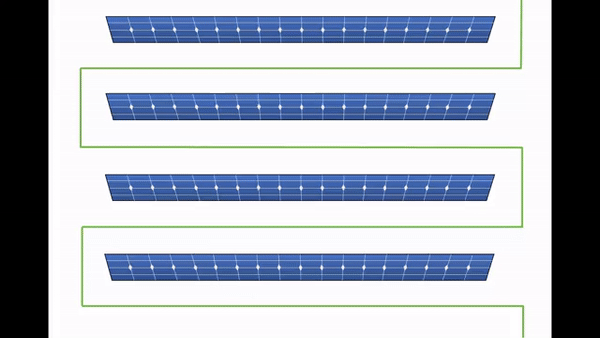

Ensure rows are horizontal in each image and the heading should remain consistent throughout the flight as shown above.
To avoid data-gaps and the need to re-fly, establish FOV using IR sensor. RGB sensors are wider than IR, so if RGB is used as a reference when mission planning, modules are cut-off in the imagery.
Same image in RGB and IR as an example here:

Note that some modules are not fully visible in IR - This will require re-flight.
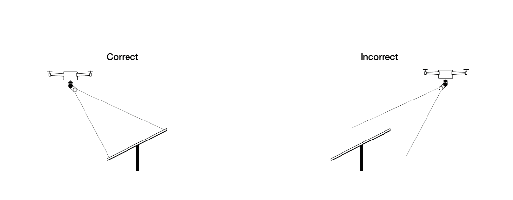
Gimbal Pitch
Perpendicular to plane-of-array as shown here
Trackers
If you are flying a site with trackers, factor in the height of the trackers when calculating the correct altitude. This will ensure sufficient overlap.
During flight, monitor the angle of the panels as it changes over the course of the day.
As the angle changes, adjust the gimbal to continue capturing a full view of the modules.
Verifying and Uploading Data to Inspection Upload Link
Each inspection order has an associated data-upload link. Inspection data must be uploaded here to be processed
Copy/Paste this link into a new browser tab
Select images to be uploaded or click-drag images into the uploader
It’s important to verify data from the field. If you’re missing data, you can refly immediately and save yourself a trip back to the site.
You’ll want to check and make sure that your flight plan provided 80/20 overlap and completely covered the site.
Using your Upload Link, drag your data into the window to see the flight path covering the solar site. Check to make sure you haven’t missed any rows.

Note that verification uses very little bandwidth, so you can verify even when you only have hotspot connectivity.